
SURGEON 25: Mastering EQ Build (Part 2) - Understanding the Core Design and Its Implications
- Eitan Brown

- Jan 18
- 6 min read
Updated: Feb 25

Welcome back! Part 1 was about how Surgeon 25 came into being. In this post, we’ll take a closer look at what’s actually inside it, and the considerations behind each design decision, along with the implications those decisions had for how the build needed to be executed.
Understanding the Core Design

Part 2 focuses on the core design of Surgeon 25 and the work required to execute it accurately. While the first post covered how the project began, this one looks at the circuit architecture it is built on, what was inherited, and why understanding that foundation was necessary before making any modifications. Many of the decisions that follow only make sense once this groundwork is in place.
Design Lineage and Inherited Architecture

The core of Surgeon 25 is an adaptation of the Sontec 250A-style parametric equalizer topology, a design that has remained in use in mastering for decades because it does its job reliably and predictably. It provides enough flexibility to address real problems, without encouraging constant adjustment or overcorrection. That balance makes it well suited to mastering work, where small, intentional moves matter more than broad tonal shaping.
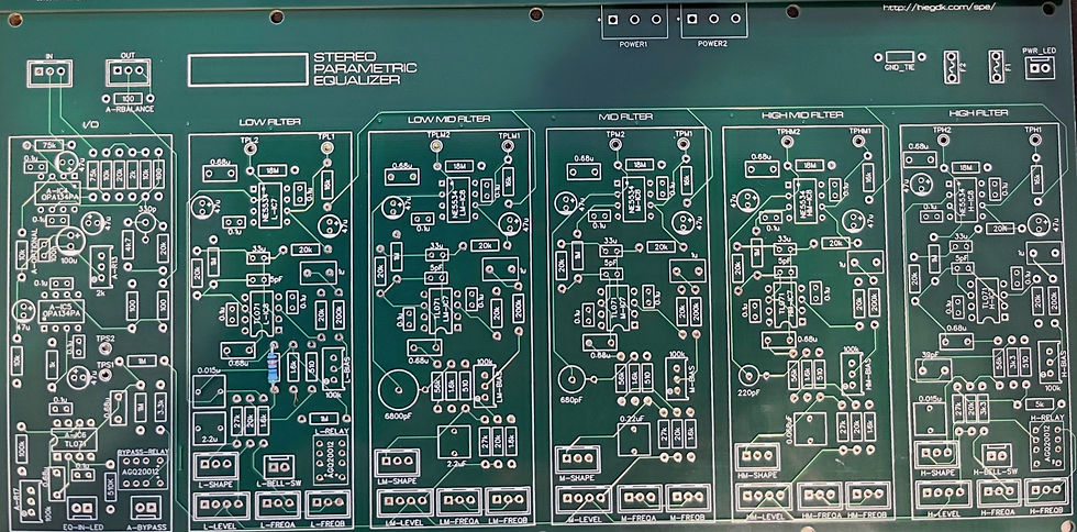
In this project, the fundamental structure of the circuit was fixed by definition. The main PCBs, designed by Hieg Khatcherian and provided to me by Uroš Đorđević, were what they were, and my task was to assemble them as faithfully and accurately as possible, with Uroš’s guidance. The number of bands, their behavior, and the overall approach to gain and frequency control were inherited directly from that design. Understanding how the circuit behaves was essential before making decisions about execution, layout, or changes elsewhere in the system. Any modifications I made were deliberately kept outside the core circuit, focusing instead on careful implementation, sourcing high-quality components, power, control, and overall integration.
Channel Architecture and Signal Flow

At a circuit level, each channel of Surgeon 25 is built as a complete, self-contained parametric equalizer. Each channel consists of five fully parametric bands, covering the full audio range, with identical topology repeated for left and right. The low and high bands include a selectable bell or shelf response, switched by relays that are controlled from the front panel. This allows those bands to function either as conventional parametric filters or as shelving EQs without altering the core signal path.
The signal enters through a balanced input stage and is routed to a summing structure that feeds all five filter bands in parallel. Rather than cascading the bands in series, each band processes the same input signal independently, and their outputs are summed back together before the final output stage. This parallel architecture minimizes interaction between bands and keeps behavior predictable, especially when multiple bands are engaged at once.
Each band is controlled by frequency, gain, and bandwidth (Q). Frequency determines where the band operates, gain sets the amount of boost or cut, and Q controls how wide or narrow the affected range is. These controls are implemented with stepped rotary switches rather than continuous potentiometers, fixing each parameter to a set of defined values. After processing through the filter network, the summed signal is passed to the output stage and presented as a balanced output.
Dual Mono as an Architectural Choice

One of the earliest architectural decisions in the build was to configure the unit as dual mono rather than as a permanently linked stereo EQ. This choice was about preserving flexibility in how the unit could be used. A dual mono structure allows the EQ to operate as a conventional stereo processor, to be placed into mid-side mode, or to be used as two independent mono equalizers when needed.
From a practical standpoint, this decision had clear consequences. Regardless of whether the unit is configured as stereo or dual mono, precise component selection and channel matching are required to ensure predictable behavior and reliable stereo imaging. In this build, matching meant ensuring that corresponding switch positions on the left and right channels produced the same electrical response. Dual mono did not change those requirements, but it did change how they were implemented: instead of additional poles on shared switches, each channel used its own set of switches. The increased number of switches introduced more potential mechanical fault points and placed extremely tight constraints on the front panel layout, leaving virtually no margin for error in panel design or machining.
This decision influenced nearly every stage of the build that followed. It affected how switches were assembled, how wiring looms were planned, how mid-side functionality could be integrated later, and how testing and calibration would be approached. Choosing dual mono early on helped define the scope of the project and set expectations for the level of precision required throughout the rest of the work.
Stepped Controls in a Mastering EQ Build

Another defining aspect of the core design was the use of fully stepped controls. In a mastering context, stepped controls serve several closely related purposes. They allow for reliable recall and repeatability, they ensure that corresponding settings between the left and right channels are precisely matched, and they enforce a finite set of deliberate choices. Each click represents a known change, with no ambiguity about where a control is set or how it relates to the opposite channel.
Stepped controls also change how decisions are made. Instead of searching for an undefined “in-between” position, the process becomes one of evaluating discrete options that are already defined. In practice, this often speeds up the workflow, because each option can be assessed quickly and decisively, which makes it easier to move forward with clear, intentional adjustments.
In this design, gain, frequency, and bandwidth are all selected using rotary switches rather than continuous potentiometers. That choice places strict demands on consistency: each step must behave the same way every time it is engaged, and corresponding steps between channels must produce the same result. Any variation becomes immediately audible when working at the small adjustment ranges typical of mastering.
Because the controls are stepped, much of the EQ’s behavior is set at the point of assembly. Using rotary switches meant measuring, selecting, and soldering matched resistors onto every switch position, rather than wiring a single component and moving on. It added a substantial amount of time and cost to the mastering EQ build, and it tightened the mechanical constraints on the front panel as well. Accepting that tradeoff was a deliberate choice. Precise channel matching, reliable recall, and a clear, decisive workflow were core to how I wanted this EQ to function, and stepped controls were essential to getting there.
Resistor Matching as a Foundational Task

Resistor matching followed directly from the decision to use stepped controls. The build uses 30 rotary switches, and each switch position needed to produce the same electrical result on both channels. The frequency controls are dual-pole switches, meaning two separate resistor networks are engaged at the same time; mismatches between those poles would shift the effective frequency or response shape. As a result, frequency switches required four-way matching across left/right channels and both poles. To populate nearly 800 resistors on the switches, and roughly 1,000 resistors across the project as a whole, I measured over 10,000 resistors by hand and selected matched sets for specific positions.
In practical terms, this meant measuring every resistor individually with the highest resolution my measurement tools allowed, and matching them as closely as possible for their intended positions. For most values, resistors were matched to within 0.01%, with a small number of more difficult values matched to within 0.02%. This level of matching goes beyond what is typically implemented in original Sontec units and other high-end commercial mastering EQs.
This stage added roughly two months to the overall build. It was a straightforward but demanding stretch of work, and it established the level of care and repetition that would carry through the rest of the project.
Transition to System-Level Design

With the core circuit understood and the control structure locked in, the focus shifted from individual components to the system as a whole. Power, grounding, mechanical layout, signal routing, and the integration of mid-side functionality became the next set of problems to solve. Part 3 looks at how those decisions took shape.

Comments