
SURGEON 25: Mastering EQ Build (Part 6) - Wiring, Calibration, and Unwelcome Surprises in Audio Assembly
- Eitan Brown

- Feb 17
- 4 min read
Updated: Feb 25

Waiting for the Panel
While I had partially assembled the unit, having finished the rear panel and mounting holes on the chassis floor, wiring could not begin until the front panel returned from Nogata Denki Kogyo. The wiring lengths depended on the exact physical position of every switch, LED, and rotary control. Guessing would have meant either excess slack everywhere or wires pulled too tight to service later.
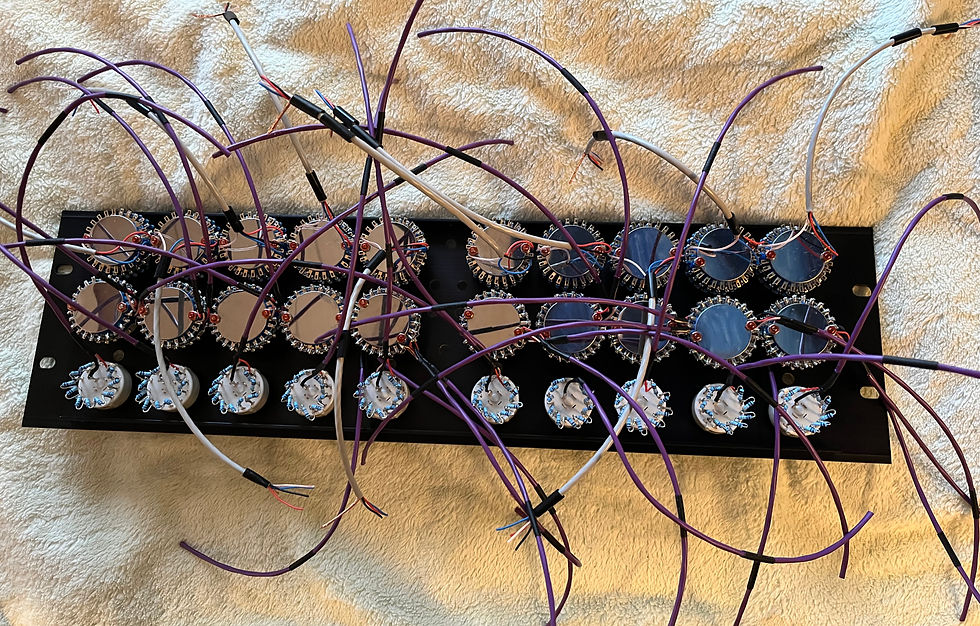
Audio Assembly

The rear panel was assembled, and the PCBs were mounted to the chassis floor. Only then could I temporarily mount every control onto it and measure each wire run deliberately before cutting.
For audio paths, the goal was short and direct, but not strained. There needed to be enough slack to lift a board for service or to redo a connector. That margin proved useful more than once. For DC wiring to toggle switches and LEDs, the priority was different: clean routing along the chassis floor, organized and separated from signal paths wherever possible.
The layout served three priorities: serviceability, signal integrity, and long-term reliability.
Choosing the Wire
For internal signal wiring, the real question was this: how should the signal actually move inside the box?
Should each run be individual hook-up wire, twisted by hand and routed as needed, or should every path begin as a contained, shielded unit?

I could have used individual 24 AWG wires and twisted them manually. That would have been electrically sufficient, and is how it is typically done in DIY audio assembly. But with this many internal runs packed tightly together, things could become visually messy, mechanically strained, and prone to crosstalk. Crosstalk is simply one signal bleeding into another when two wires sit too close together.
Mogami cable assemblies are factory twisted, shielded, and mechanically stable. Each run became a self-contained unit with its own shielding. That reduced the chance of signals bleeding into adjacent runs, simplified routing, and kept the interior disciplined.

Once I committed to Mogami, the rest was straightforward. Mogami makes a series of internal console wiring cables. 2799 contains two conductors plus shield. Mogami 2944 contains four conductors plus shield. The frequency and Q switches required three conductors per pole, so 2799 made sense, using the shield as the third conductor with heat shrink for insulation. The gain switches required four conductors, so 2944 was the natural fit.
Yes, they are 26 AWG, thinner than the more typical 24 AWG used in some audio wiring. For the short internal runs involved here, current draw and impedance made that difference negligible compared to the shielding and mechanical stability the Mogami console wires provided.

The result was electrically sound and physically disciplined.
Crimping, Connecting, Repeating

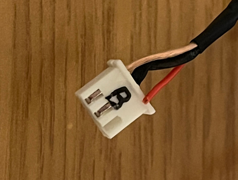
Every inter-board connection used JST connectors.
That meant crimping and assembling hundreds of terminals by hand.
There is no shortcut for that stage. It is repetitive and slow. Each crimp must be mechanically secure on its own. Each housing must click fully into place. Each cable must be labeled or traceable.
This was one of the least glamorous phases of the entire project. It was also one of the most important. A poorly crimped terminal can mimic far more serious circuit faults later. Spoiler alert: a couple of them did.
Precision here was quiet insurance.
Full-System Power-Up
The very first power-up had already revealed layout mistakes in the DC distribution board that required rerouting and revision, which I covered in Part 4. Those were resolved long before full wiring began.
Now came the first full-system power-up after complete assembly.

No explosion. No smoke. No tripped breaker. Relief.
The ±15 V rails were present, stable, and reaching every board as intended.
Calibration
Calibration began with DC offset adjustments. DC offset is the small unintended DC voltage that can appear at an audio output even when no signal is present. Ideally, every stage should sit at 0 V DC so the signal can swing symmetrically. In practice, component tolerances and bias currents shift that operating point slightly.
Each of the ten filter bands, five per channel, was measured and trimmed individually, followed by the two channel outputs, twelve adjustment points in total. With no signal applied, each stage was brought to within a few millivolts of zero to preserve headroom and symmetry.

Unity gain was set carefully. With EQ bypassed, the output level matched input as precisely as the measurement equipment allowed.
Switch positions were stepped methodically. Boost and cut were measured. Left-to-right tracking was compared. Channel-to-channel matching was checked next.
Most values landed where expected.
But not all.
The Unease
At first, it was subtle.
The two channels did not match in level. With EQ engaged, one channel sat about 1 dB lower than the other. Not catastrophic, but unacceptable for a mastering EQ.
A few of the frequency and gain switches were exhibiting anomalous behavior, either mechanically or electrically. That, too, was unacceptable.

The wiring had been deliberate. The rails were stable. Offsets were trimmed. Unity gain was verified.
And yet, the unit did not behave with the precision I had built into it.

Assembly felt like the final step. It wasn’t. Investigation and troubleshooting were next.
That is where the story continues.


Comments